
A pressure sensor can pass every bench test on your bench and still fail weeks into field service. That gap is one of the most common and expensive problems in sensor deployment, and understanding the real pressure sensor failure causes behind it is the first step toward preventing warranty returns, unplanned downtime, and lost confidence in your product.
Bench testing confirms that a device works under controlled, benign conditions. Field service subjects that same device to vibration, thermal swings, moisture, aggressive media, and electrical noise, often all at once. No single root cause explains every failure. Instead, a handful of distinct mechanisms tend to appear once a sensor leaves the lab.

Why Bench Testing Misses Real-World Pressure Sensor Failure Causes
A bench test is usually short, clean, and stable. Room temperature holds steady. Pressure is applied smoothly. The sensor sits still on a padded surface, wired with a short lead to a calibrated reference. Those are exactly the conditions a field installation does not provide.
The mismatch matters because most pressure sensor failure causes are driven by stressors that a quiet bench simply never applies. A unit can read within 0.25% of full scale all afternoon on your test stand and then drift, glitch, or fail outright when it meets the real environment.
Mechanical Stressors
- Vibration and mechanical shock. Continuous vibration can fatigue solder joints, wire bonds, and diaphragm welds. Mechanical shock from water hammer, slamming actuators, or transport can crack a sensing element that a static bench test never loads.
- Pressure spikes and pulsation. Pumps, valves, and compressors generate transient spikes that can far exceed the nominal working pressure. Repeated pulsation drives fatigue in the diaphragm, even when each individual spike stays below the proof pressure.
Thermal Stressors
- Temperature cycling. Repeated heating and cooling expands and contracts dissimilar materials at different rates, stressing seals, bonds, and electrical connections over thousands of cycles.
- Thermal gradients. A steep temperature difference across the sensor body, for example a hot process fluid against a cold ambient, can induce measurement error and mechanical stress that a uniform-temperature bench test cannot reproduce.
Ingress and Media Stressors
- Moisture ingress and condensation. Humidity, washdown, and daily thermal cycling can pull moisture past a seal. Condensation inside the housing can corrode electronics and short circuits.
- Media incompatibility. A wetted material that tolerates clean test fluid may corrode or swell when exposed to the actual process media, whether that is a solvent, a chloride-bearing fluid, or a gas with trace contaminants.
- Seal degradation. Elastomer seals age, take a compression set, and lose sealing force with heat and chemical exposure, opening a slow path for ingress that appears only after months in service.
Electrical and Installation Stressors
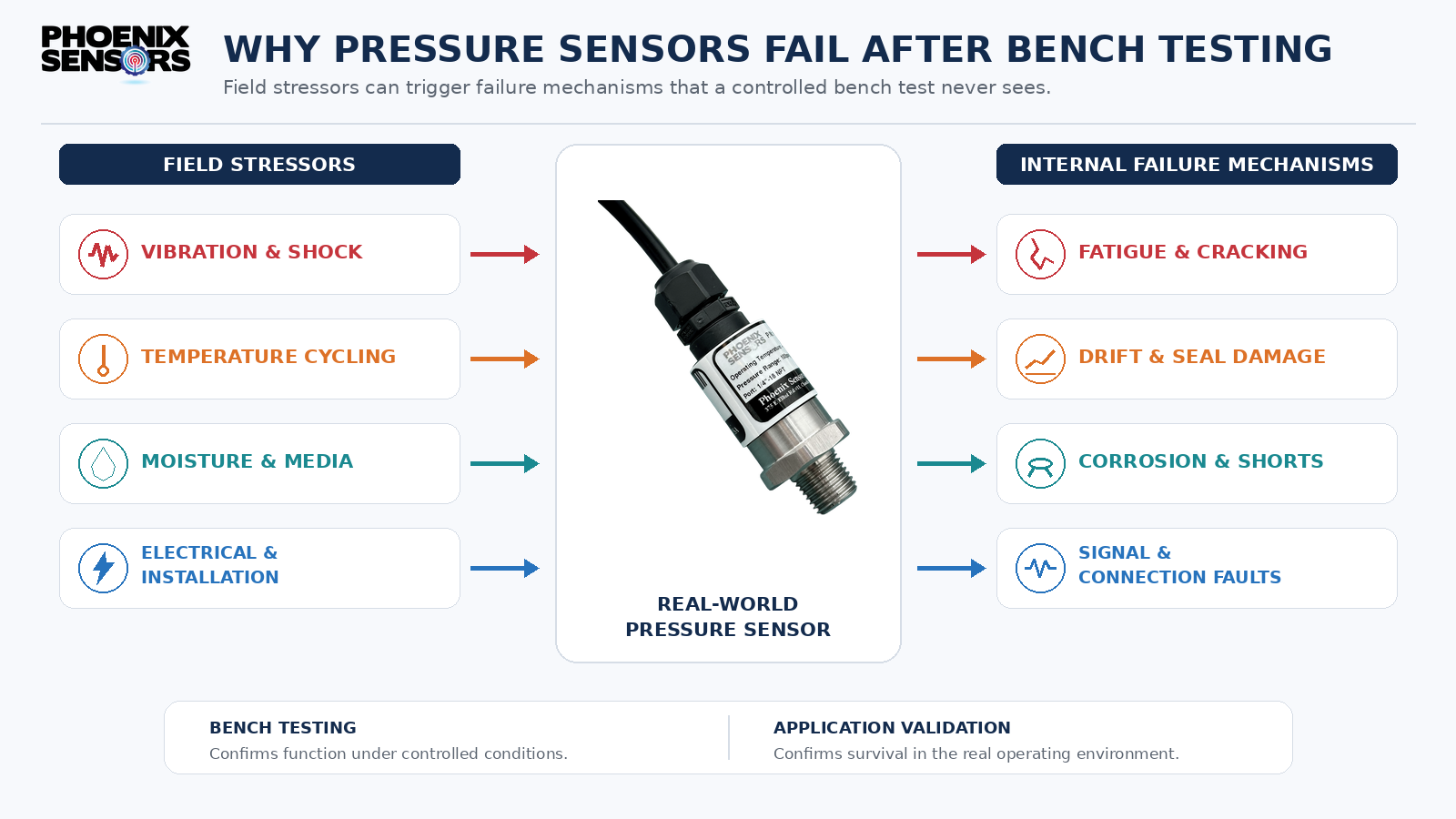
- Electrical noise. Nearby motors, drives, and switching power supplies inject noise that a shielded bench setup never sees, producing unstable readings or false alarms.
- Cable and connector stress. Flexing, pulling, and vibration at the cable entry can fatigue conductors and back out connector pins, creating intermittent opens.
- Incorrect mounting and installation torque. Over-torque can distort the sensing element and shift the zero point; under-torque can leak. Mounting orientation and rigidity also change how vibration couples into the device.
- Improper venting. A gauge sensor relies on a clear vent to reference atmosphere. A blocked or moisture-fouled vent shifts readings and can admit water.
- Supply-voltage problems. Sag, ripple, reverse polarity, and transients on the supply line can push a sensor out of spec or damage it, none of which show up on a clean bench supply.
Combined and Intermittent Effects
Real installations rarely apply one stressor at a time. Heat plus vibration, for instance, softens adhesives while simultaneously fatiguing them, so the combination fails faster than either would alone. Many intermittent failures also depend on a specific coincidence, a certain temperature during a certain vibration state, that a short-duration functional test is statistically unlikely to catch.
Lab Conditions vs. Field Conditions
The table below shows how a typical bench environment compares with the conditions a sensor actually meets in service. The right-hand column is where most field failures originate.
| Parameter | Typical Bench Test | Possible Field Condition |
|---|---|---|
| Temperature | Stable room temp, ~20-25°C | -40°C to +125°C, cycling daily |
| Thermal gradient | Uniform | Hot media vs. cold ambient across body |
| Pressure profile | Smooth, slow ramp | Spikes and pulsation above nominal |
| Vibration | None (still bench) | Continuous, plus periodic shock |
| Humidity / ingress | Dry lab air | Washdown, condensation, submersion
|
| Media | Clean air or water | Solvents, chlorides, contaminated gas |
| Cable / connector | Short, unstressed lead | Long runs, flexing, pull, vibration |
| Supply voltage | Clean regulated bench supply | Ripple, sag, transients, reverse polarity |
| Electrical environment | Shielded, quiet | Motors, VFDs, switching noise |
| Duration | Minutes to hours | Months to years, continuous duty |
How Application Validation Differs From Functional Testing
Functional testing answers a narrow question: does the unit work right now, under these conditions? Application validation answers a harder one: will this unit keep working under the conditions it will actually see, for as long as it must?
That shift requires defining the application before you evaluate the sensor. At minimum, specify:
- Pressure range the sensor will actually experience, not just the nominal setpoint.
- Proof pressure and expected spike magnitude, so the design has margin above the worst case.
- Media and every wetted material it contacts, including contaminants and cleaning agents.
- Temperature range and cycling profile, plus any thermal gradients across the body.
- Vibration and shock spectrum for the mounting location.
- Ingress protection needed for the environment, matched to a defined IP rating.
- Wiring, including cable length, routing, shielding, and connector type.
- Duty cycle, whether intermittent or continuous.
- Expected life, so accelerated testing can target a realistic number of cycles and hours.
With those defined, validation uses methods that deliberately reproduce field stress: thermal cycling chambers, vibration tables, pressure-cycle fatigue, and combined-environment testing. Established methods such as the environmental test procedures in MIL-STD-810 or IEC 60068.
If you are still choosing a device, our pressure sensor selection guide walks through matching these parameters to a sensor construction.
Questions to Ask Before Approving a Sensor Design to Avoid Pressure Sensor Failures
Before you sign off, run the design against these questions:
- What is the worst-case pressure spike, and how much margin sits between it and proof pressure?
- Is every wetted material confirmed compatible with the real media, including cleaning chemicals?
- What temperature range and cycling profile will the sensor see, and has it been tested there?
- Will vibration or shock at the mounting point exceed the qualification level?
- Does the IP rating match the actual ingress exposure, including washdown and condensation?
- Are cable length, routing, and connector type validated for the mechanical and electrical environment?
- Is the supply protected against reverse polarity, transients, and ripple?
- Has the design been tested for the expected life, in cycles and hours, not just a short functional check?
- Have combined stressors, such as heat plus vibration, been tested together rather than separately?
FAQ: Common Questions About Pressure Sensor Failures
If a pressure sensor passes bench testing, why does it still fail in the field?
Bench testing verifies function under stable, benign conditions. Field service adds vibration, thermal cycling, moisture, aggressive media, and electrical noise, often simultaneously. Those stressors, not a single fault, drive most real-world failures.
What is the single most common pressure sensor failure cause?
There isn’t one. Failures come from distinct mechanisms, mechanical fatigue, seal degradation, media incompatibility, ingress, and electrical stress among them. Which one dominates depends entirely on the application, which is why validation must be application-specific.
How is application validation different from calibration?
Calibration confirms measurement accuracy at a point in time. Application validation confirms the sensor will survive and stay accurate under the full set of environmental and operational stresses it will face over its service life.
Work With Phoenix Sensors to Avoid Pressure Sensor Failure Causes
Phoenix Sensors can help you evaluate application-specific sensor construction against the conditions your device will actually face. Contact us to share your application conditions, drawings, failure symptoms, and any test data with our team, and we can discuss materials, mounting, sealing, and testing approaches suited to your environment. We can help evaluate a construction for your application, but no design should be considered field-ready until it has been tested and validated against your real conditions. To discuss a custom build, see our custom pressure sensor and engineering services.